Figure 4.4 shows the DB62 external expansion board and Table 4.9 lists the description.
Figure 4.4 DB 62 external expansion board
Table 4.9 The external expansion interface description
PIN |
Name |
Function |
Voltage/Current |
1 |
EX_IN9(DIN9) |
Digital input |
0V,24V/<100mA |
2 |
PGND |
Negative of the logic power |
GND/5A |
3 |
EX_IN10(DIN10) |
Reset signal |
0V,24V/<100mA |
4 |
PGND |
Negative of the logic power |
GND/5A |
5 |
EX_IN11(DIN11) |
External I/O control signal. Namely, Dobot M1 activates external I/O control function |
0V,24V/<100mA |
6 |
PGND |
Negative of the logic power |
GND/5A |
7 |
EX_IN12(DIN12) |
Continue signal |
0V,24V/<100mA |
8 |
PGND |
Negative of the logic power |
GND/5A |
9 |
EX_IN13(DIN13) |
Pause signal |
0V,24V/<100mA |
10 |
PGND |
Negative of the logic power |
GND/5A |
11 |
EX_IN14(DIN14) |
Stop signal After this signal is triggered, Dobot M1 will stop offline running while the external I/O control will remain in force. At this point, you can use M1Studio to control Dobot M1 in Dobot mode or trigger DIN 15 to make Dobot M1 run in offline mode again |
0V,24V/<100mA |
12 |
PGND |
Negative of the logic power |
GND/5A |
13 |
EX_IN15(DIN15) |
Start signal, for running in offline mode Before triggering this signal, please trigger DIN 11 first |
0V,24V/<100mA |
14 |
PGND |
Negative of the logic power |
GND/5A |
15 |
EX_IN16(DIN16) |
Digital input |
0V,24V/<100mA |
16 |
PGND |
Negative of the logic power |
GND/5A |
17 |
ON_OFF+ |
Positive of the power signal |
0V~24V/<100mA |
18 |
GND |
Negative of the analog power |
GND/1A |
19 |
GND |
Negative of the analog power |
GND/1A |
20 |
GND |
Negative of the analog power |
GND/1A |
21 |
GND |
Negative of the analog power |
GND/1A |
22 |
NC2 |
Relay K2 Normally Closed |
AC: 250V/5A DC:30V/5A |
23 |
NO2 |
Relay K2 Normally Open |
AC: 250V/5A DC: 30V/5A |
24 |
COM2 |
Common terminal |
AC: 250V/5A DC: 30V/5A |
25 |
GND_EMC |
Earth ground |
GND/5A |
26 |
FPGA_OUT1(DOUT11) |
Digital output |
0V,24V/2mA |
27 |
VCC_24V |
Positive of the logic power |
24V/3A |
28 |
FPGA_OUT2(DOUT12) |
Digital output |
0V,24V/2mA |
29 |
VCC_24V |
Positive of the logic power |
24V/3A |
30 |
FPGA_OUT3(DOUT13) |
Digital output |
0V,24V/2mA |
31 |
VCC_24V |
Positive of the logic power |
0V,24V/2mA |
32 |
FPGA_OUT4(DOUT14) |
Digital output |
0V,24V/2mA |
33 |
VCC_24V |
Positive of the logic power |
24V/3A |
34 |
FPGA_OUT5(DOUT15) |
Digital output |
0V,24V/2mA |
35 |
VCC_24V |
Positive of the logic power |
24V/3A |
36 |
FPGA_DOUT6(DOUT16) |
Digital output |
0V,24V/2mA |
37 |
VCC_24V |
Positive of the logic power |
24V/3A |
38 |
DAC_OUT1 |
Analog output, reserved |
- |
39 |
GND |
Negative of the analog power |
GND/1A |
40 |
DAC_OUT2 |
Analog output, reserved |
- |
41 |
GND |
Negative of the analog power |
GND/1A |
42 |
ON_OFF- |
Negative of the power signal |
0V~24V/<100mA |
43 |
IN_A/D1(AIN1) |
Analog input |
0V~10V/<100mA |
44 |
IN_A/D2(AIN2) |
Analog input |
0V~10V/<100mA |
45 |
IN_A/D3(AIN3) |
Analog input |
0V~10V/<100mA |
46 |
IN_A/D4(AIN4) |
Analog input |
0V~10V/<100mA |
47 |
EX_A1+ |
Signal input for A phase of external encoder1, reserved |
- |
48 |
EX_A1- |
Inversion signal input for A phase of external encoder1, reserved |
- |
49 |
EX_B1+ |
Signal input for B phase of external encoder1, reserved |
- |
50 |
EX_B1- |
Inversion signal input for B phase of external encoder1, reserved |
- |
51 |
EX_OUT1(DOUT1) |
Digital output |
0V,24V/2mA |
52 |
VCC_24V |
Positive of the logic power |
24V/3A |
53 |
EX_OUT2(DOUT2) |
Digital output |
0V,24V/2mA |
54 |
VCC_24V |
Positive of the logic power |
24V/3A |
55 |
EX_OUT3(DOUT3) |
Digital output |
0V,24V/2mA |
56 |
VCC_24V |
Positive of the logic power |
24V/3A |
57 |
EX_OUT4(DOUT4) |
Digital output |
0V,24V/2mA |
58 |
VCC_24V |
Positive of the logic power |
24V/3A |
59 |
EX_OUT5(DOUT5) |
Digital output |
0V,24V/2mA |
60 |
VCC_24V |
Positive of the logic power |
24V/3A |
61 |
EX_OUT6(DOUT6) |
Digital output |
0V,24V/2mA |
62 |
VCC_24V |
Positive of the logic power |
24V/3A |
63 |
EX_OUT7(DOUT7) |
Running status signal |
0V,24V/2mA |
64 |
VCC_24V |
Positive of the logic power |
24V/3A |
65 |
EX_OUT8(DOUT8) |
Alarm signal |
0V,24V/2mA |
66 |
VCC_24V |
Positive of the logic power |
24V/3A |
67 |
VCC_24V |
Positive of the logic power |
24V/3A |
68 |
PGND |
Negative of the logic power |
GND/5A |
69 |
CAN2_H |
CAN bus, reserved |
- |
70 |
CAN2_L |
CAN bus, reserved |
- |
71 |
VCC_5V |
Positive of the logic power |
5V/2A |
72 |
EX_A2+ |
Signal input for A phase of external encoder2, reserved |
- |
73 |
EX_A2- |
Inversion signal input for A phase of external encoder2, reserved |
- |
74 |
EX_B2+ |
Signal input for B phase of external encoder2, reserved |
- |
75 |
EX_B2- |
Inversion signal input for B phase of external encoder2, reserved |
- |
76 |
EX_IN1(DIN1) |
Digital input |
0V,24V/<100mA |
77 |
PGND |
Negative of the logic power |
GND/5A |
78 |
EX_IN2(DIN2) |
Digital input |
0V,24V/<100mA |
79 |
PGND |
Negative of the logic power |
GND/5A |
80 |
EX_IN3(DIN3) |
Digital input |
0V,24V/<100mA |
81 |
PGND |
Negative of the logic power |
GND/5A |
82 |
EX_IN4(DIN4) |
Digital input |
0V,24V/<100mA |
83 |
PGND |
Negative of the logic power |
GND/5A |
84 |
EX_IN5(DIN5) |
Digital input |
0V,24V/<100mA |
85 |
PGND |
Negative of the logic power |
GND/5A |
86 |
EX_IN6(DIN6) |
Digital input |
0V,24V/<100mA |
87 |
PGND |
Negative of the logic power |
GND/5A |
88 |
EX_IN7(DIN7) |
Digital input |
0V,24V/<100mA |
89 |
PGND |
Negative of the logic power |
GND/5A |
90 |
EX_IN8(DIN8) |
Digital input |
0V,24V/<100mA |
91 |
PGND |
Negative of the logic power |
GND/5A |
92 |
PGND |
Negative of the logic power |
GND/5A |
93 |
VCC_24V |
Positive of the logic power |
24V/3A |
94 |
RS-485_A |
RS485A bus, reserved |
- |
95 |
RS-485_B |
RS485B bus, reserved |
- |
96 |
GND |
Negative of the analog power |
GND/1A |
97 |
NC1 |
Relay K1 Normally Closed |
AC: 250V/5A DC: 30V/5A |
98 |
NO1 |
Relay K1 Normally Open |
AC: 250V/5A DC: 30V/5A |
99 |
COM1 |
Common terminal |
AC: 250V/5A DC: 30V/5A |
100 |
GND_EMC |
Earth ground |
GND/5A |
NOTICE
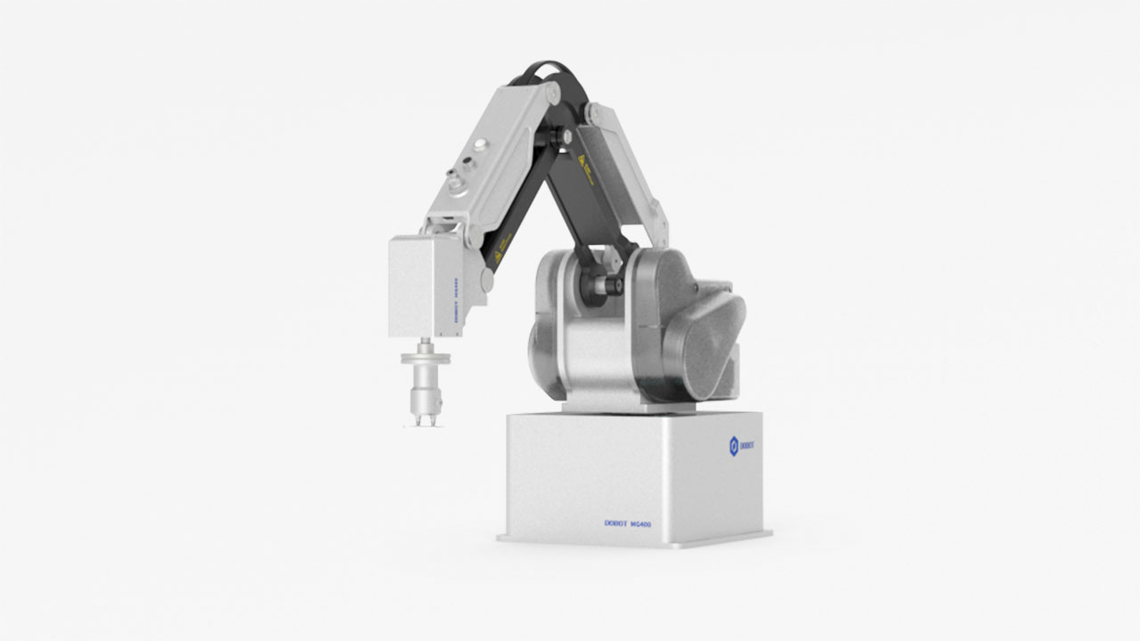
DOUT9 and DOUT10 are used to control relay K1 and K2 respectively, which are internal encapsulated interfaces. If you use relay for power supply or other applications, you can use the COM, NC, NO interfaces directly on the external expansion board after connecting it to Dobot M1. If you have to debug the relay K1 and K2, you can debug OUT09 and OUT10 on the M1Studio > I/O Assistant page. For details, please see 6.10.6 Example of Relay Connection.
All input and output interfaces of the Dobot M1 only can be used for signal control and cannot be regarded as power supply. You can use relays on the external expansion board for power supply. Take relay K1 as an example, the circuit diagram is shown in Figure 4.5.
Figure 4.5 Circuit diagram